有竞争力的称重传感器产品配置
The Simple Column Cell

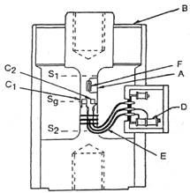
Figure 33. Simple column cell
All Interface, Inc. products are designed around either the bending beam, the shear beam, or the pipe column. In order to understand the reasons behind this decision, we need to understand the design of the plain column cell, the other major type of load cell.
The cross-section view in Figure 33 shows the components of the simple column cell. The “flexure” is the heavy column (A) running up the center of the cell, with massive blocks at the top and bottom and a thin, usually square, column in the center. This column, plus the heavy outer shell and the diaphragms (B) are the basic support elements for the measurement flexure, the column (A) which runs from S1 to S2 .
The column stress between S1 and S2 is about the same anywhere along its length, so the main gages (C1 and C2) are placed in the center, at Sg. Compensation for the nonlinearity of the column design is accomplished by the semiconductor gage (F).
Loads are applied by the customer’s fixtures which can be screwed into the threaded holes at the top and bottom ends of the column.
The “doghouse” on the side of the casing contains the bridge compensating resistors (D) which are wired (E) to the gages.
At first glance, this might seem to be an uncomplicated design. The physical parts themselves are relatively simple to produce. However, several characteristics seriously restrict its usability.
- The thermal path from the column (A) to the outer case is very long and has a thin cross section, thus causing the temperature gradients to take a long time to stabilize. If heat is applied to one side of the case, the case itself will expand on the hot side, and a moment will be applied to the column, causing a zero shift.
- If heat is applied to the doghouse side of the cell, the compensating resistors will change resistance before the column sees the temperature change. Thus, the resistors will be attempting to compensate for a change which has not even occurred yet, causing a zero shift and an output shift.
- The diaphragms are an important part of the support, to keep moment loads away from the column. However, since they are outside of the gaged areas of the column, they are a non-gaged parallel path which introduces their errors (nonlinearity, hysteresis, and thermal response) directly into the measurement path. The diaphragms cannot be strong enough to protect the column from pure moment loads, without introducing significant errors.
- Changes in pressure due to barometric change or altitude testing act on the diaphragm, causing a zero shift. For example, a six inch diameter diaphragm would induce a force change of 375 pounds into a column cell in a test from sea level to space orbit altitude.
- The cell is quite tall, making it more difficult to integrate into compact testing equipment.
- Since the cross sectional area of the column changes with loading and is different between tension and compression modes, the output is non-linear and unsymmetrical. Non-linear semiconductor gages can be used to compensate the non-linearity, but only in one mode.
Advantages of the LowProfile Cell
By contrast, the LowProfile cell compares dramatically better in all respects to the simple column cell.
- The thermal path is massive and surrounds the whole cell. The thermal path between the outside surface and all the gages is very short. Temperature gradients are almost non-existent, and they settle out very quickly.
- Compensating resistors are mounted on the flexure, in close proximity to the gages.
- The diaphragms are used only as a sealing mechanism, not as a support, so they do not introduce appreciable errors into the cell.
- There are two opposing diaphragms, one on the top and one on the bottom of the cell. Their opposing forces due to pressure are equal and opposite, thus canceling out pressure effects.
- The cell is short and squat, thus making it much easier to integrate into system designs. Column cells range in height from 6" to 24", compared to a Low Profile cell’s height with base, of 2.5" to 6.5".
- The design is intrinsically moment canceling and is rotationally symmetrical. In addition, moment cancellation is enhanced by special testing and adjustment in the factory.
- Since the cross sectional area of the flexure does not change appreciably with loading, the output is intrinsically more linear and is also symmetrical between tension and compression modes.
- The output of the shear beam cell is up to 2.5 times the output of a column cell at the same stress level in the flexure.
- The overall Low Profile design is more compact, with all the components bonded to the flexure structure, thus making it better able to withstand the 100 million cycle fatigue life.


